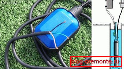
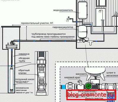
Submersible pump connection diagram
Any suburban housing owner knows that submersible-type pumping equipment is universally used in well water supply systems. In addition, this equipment can be operated in the heating networks of private households.
The so-called direct connection scheme of the submersible pump to the power grid (without involvement of auxiliary equipment) is quite simple and involves direct connection to the contact group of supply conductors, referred to as "phase", "zero" and "grounding".
Note that this method of connection can be used not in all cases of arrangement of water intake systems. On the contrary, most often pumping equipment is used in conjunction with automation of one type or another, which noticeably improves the operational characteristics of the system, as well as enhances its serviceability. As a rule, such extended schemes include the following components:
- electrical contactors (starters);
- switches (intermediate type relay);
- level and pressure sensors;
- hydroaccumulator.
Purpose of automation
The use of automation elements installed in the equipment power supply circuits will allow you to connect a submersible pump in such a way that the system will operate in automatic mode.

The basis of this scheme is a contactor with a normally open contact group, to the input of which leads the supply conductors (phase, zero and ground). Well, the pump itself is connected to the output of the contactor, which receives power from the mains through it.
The use of such a pump connection scheme assumes the presence of a special accumulator, which incorporates a check valve. It is in this unit that the pressure switch is installed, which controls the operation of the contactor group, which supplies and removes voltage from the pump.
The functioning of the entire system in automatic mode is as follows.
- When the pressure in the system drops to the minimum level, the relay sensor gives a signal to turn on; at the same time, the working group contacts close the pump power supply circuit.
- As water enters the system, the pressure in the accumulator gradually increases.
- When the pressure reaches its upper threshold (limit value) by a signal from the pressure sensor, the contactor operates to shut off. Its contacts open and the equipment is automatically disconnected from the mains.
For domestic water systems designed for large volumes of liquid, the electrical circuit on the float sensors is more suitable, providing automatic control of the level of liquid in the collection tank (hydroaccumulator). The schematic diagram of the connection of the pumping equipment in this case does not differ significantly from the previous one, except for the fact that instead of the pressure relay it is installed a liquid level sensor.
It is worth noting that to connect the power supply to the pump of the submersible (borehole) type, you will need special-grade cables. Waterproof wire under the designation runway or KVV is best suited for this purpose. Good performance for waterproofing is also imported cable brand AQUA RN8.
Assembly design with automation elements
In the event that it is planned to assemble the water supply system, the launch and shutdown of which would be carried out from the water supply valve, then you will have to purchase a special hydraulic accumulator used in conjunction with a pressure relay.
At the same time, the connection of automation to the pump can be organized from a concrete well located in the immediate vicinity of the well itself with the pump.
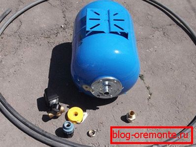
To assemble a water supply system based on a submersible pump, you will need the following devices and components:
- typical hydroaccumulator of the corresponding capacity;
- pressure switch, designed to work with the type of hydroaccumulator chosen by you;
- special transition coupling (the so-called "American") with an installation size of 1 ";
- one more coupling equipped with a collet chuck;
- special brass adapter;
- plastic pipes, fittings, tape FUM.
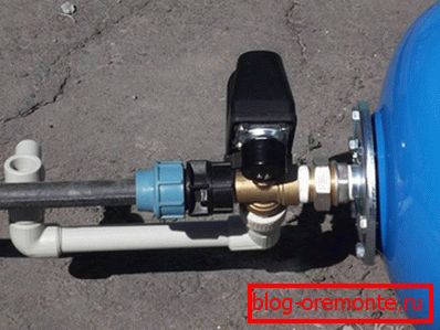
The main installation work on the assembly of the pump control circuit is usually not carried out in a well prepared in advance, but at the top, in open space. Upon completion of the assembly of this part of the structure, you will be able to lower it to the bottom of the well, where in cramped conditions you will only have to connect it to the pump.
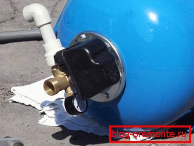
Work on the assembly of control circuits and control, it is customary to begin with strapping the accumulator; at the same time, in order to reliably seal the connections and facilitate subsequent maintenance of the system, all threaded connections are sealed using a special tape FUM.
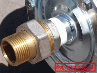
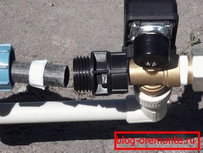
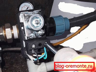
Note that the pressure switch is connected to the pressure accumulator not directly, but through a special adapter called “American”. The use of a transition element makes it easy to dismantle the connection if necessary, and also greatly simplifies all operations for connecting and setting up automation.
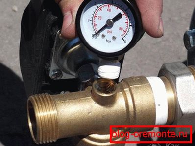
When installing the pressure switch, try to place it in such a way that, if necessary, you can “take” the pressure gauge at any time (without dropping to the bottom of the well). You should also pay attention to the fact that the reliability and tightness of the connection of the relay with the strapping should be provided with a special gasket.
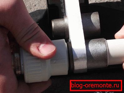
In the future, to form a consumer's water line (connected to the outlet from the pressure switch), you will need to make a special composite bend brazed from the fitting and a piece of plastic pipe. At the end of the plastic pipe, a sleeve with an external thread (type MPH) is soldered, which is hermetically attached to the outlet from the pressure switch (see photo on the left).
In this part of the work that should be carried out outside the well, can be considered completed.
Photo Structure


Connecting the structure to the pump
All upcoming operations to connect the assembled structure to the pump will have to be performed directly in the well. If necessary, you can break (unsolder) the existing wiring into two separate lines, one of which goes straight to the house, and the second can be used for watering the garden plot. To disable this branch for the winter period, it is necessary to provide a separate shut-off valve.
At the final stage of installation work you need to connect the electrical part of the circuit to the pressure switch. To do this, first of all it is necessary to remove the regulator cover, thereby ensuring free access to the connecting terminals of the device.
In the lower part of the housing there are openings for the input of power supply wires and a signal cable from the pump. Carefully feed all wires into these holes and connect their ends to the appropriate terminals. Most often, the terminals for connecting the signal wire from the pump are designated as "MOTOR", and the terminals for connecting the network cable - as "LINE".
Upon completion of these works, you will only have to replace the cover of the relay-regulator.
Video
The assembly of the pump group for connecting a submersible pump is demonstrated here:
Continuation of the video: