Reinforced concrete support: the main types and features of
Lighting and power lines have been used since electricity and lighting appeared everywhere. And, if at first the poles for the installation of wiring were made mainly of wood, then at the present time more technologically advanced materials are used for the production of these structures.
However, this is not surprising, since metal and reinforced concrete supports, in comparison with the structures characteristic of the first half of the last century, become higher, stronger and more resistant to significant loads.
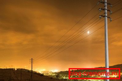
Consider what are the features of modern lighting poles and power lines, as well as what and how they are made.
Features of lighting poles and power lines
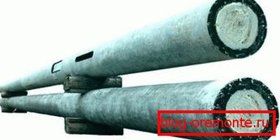
It is no secret that power lines are cable (recessed into the ground) and air. Special reinforced concrete light supports have found universal application in the construction of overhead power lines.
Installation of reinforced concrete supports can be performed in those regions where the calculated air temperature does not fall below -55 ° C. This limitation is due to the main features of the production material. Concrete is characterized by the presence of multiple micropores and, as a result, a tendency to destruction at critical temperature fluctuations.
The basis of such structures is a centrifuged or vibrated rack, made with the use of dense heavy cement mortars, reinforced with welded metal structures.
Important: The structures erected with the use of centrifuged racks (used for the construction of transmission lines 35-110 kV) are characterized by special strength and durability.

Power transmission poles, except for centrifuged and virirovanny racks, may consist of the following structural elements:
- subcoal;
- consoles;
- support-anchor plates;
- crossbars;
- anchors for fixing delays;
- lower concrete cover (thrust bearing);
- a wide range of metal structures, including cable-resistant, extension brackets, end caps, clamps, drawbars, internal connections, attachment points.
Installation of reinforced concrete pillars into the ground is carried out by installing the structure in a pre-drilled cylindrical pit with subsequent backfilling of sand and gravel in the resulting sinuses.
In order to ensure the necessary strength of the installation of structures on weak soils, the underground part of the VL supports is strengthened by means of girders caught in semi-clamps. Clamps or through-bolts are used to fasten metal structures.
Main characteristics
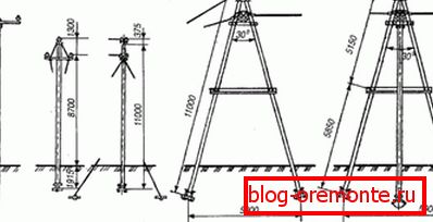
Reinforced concrete supports - are made using high-quality concrete, reinforced with wire rod and reinforcing bars.
Among the main advantages of these structures the following qualities should be noted:
- reasonable price in comparison with all-metal counterparts;
- corrosion resistance;
- resistance to long-term exposure to chemicals;
- resistance to excessive moisture;
- resistance to temperature fluctuations.
Important: The main disadvantage of supports made with the use of reinforced concrete is low strength in accordance with the mass of the structure as a whole. In addition, the high weight and dimensions of such products turn into significant expenditure during the transportation.
Main varieties
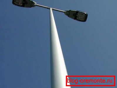
In addition to the fact that reinforced concrete lighting poles are commonly used, poles for power lines are used.
Such facilities are divided into the following categories:
- Intermediate supports - used in the construction of straight sections of the route of overhead lines.
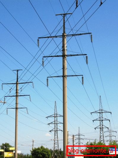
Such structures are not designed for the load directed along the power lines and are used exclusively for the installation of wires and fixing cables. Today, about 80% of all power lines are mounted on such concrete pillars.
- Anchor type supports used in the construction of straight sections of the route of overhead lines to ensure the transition through natural barriers or engineering structures. Also, these pillars are widely used in those parts of the route where it is necessary to change the number, brand and cross-section of wires.

Of all categories of reinforced concrete pillars, reinforced concrete anchor supports are of increased strength.
- Angle supports - installed on those areas where the track changes its direction. The columns of this type account for the resulting loads of gravity of the wires from the interfacing adjacent spans.
If the route is characterized by a small angle of rotation (not more than 30 °), then the load on the supports is small, and therefore angular intermediate supports can be used. For larger angles above 30 °, anchor angle supports are used with a stronger structure and anchored wires.
- End bearing - This is a type of anchor pillars.

Such structures are located mainly at the beginning and end of power lines. Facilities of this type are designed for unilateral loads.
- Special supports used to perform special tasks.
Construction features
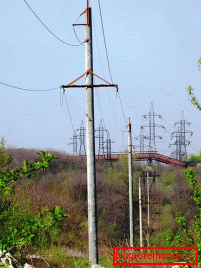
In accordance with the structural features of reinforced concrete pillars of overhead lines are divided into the following categories:
- portal with delays;
- portal with internal links without delays;
- single and multi-rack with delay;
- single and multi-rack without delays.
Manufacturing technology of overhead lines made of metal reinforced concrete
So, after we have decided on the technical and operational characteristics of reinforced concrete pylons, intended for laying overhead lines, we will consider the technology of their manufacture on the example of modification of CB 95.
Step by step production instruction. The first - the preparatory stage involves the following work.
Preparation of the working mixture:
- Preparation of Portland cement, inert materials, chemical. additives and water in accordance with the proportions given in the project documentation;
- Dosing of components and loading into the mixer;
- Bringing the mixture to a uniform consistency and unloading into the paver.
Preparation of reinforcing metal structures:
- Cutting rebar of the required class into segments of the desired size;
- Preparation of anchor heads;
- Formation of contour spirals;
- The formation of loops and preparation of the rod ground loop.
Cooking forms:
- Cleaning the internal volume of the form;
- Lubrication of internal volume by means of preventing adhesion of concrete;
- Distribution of spirals;
- Conducting isothermal heating of the rods;
- Distribution of heated rods on pre-laid stops;
- Threading the helix between the rods, followed by fastening to the rods at three points;
- The distribution of liners on the ends of the form;
- Installation of tubes and technological loops with their obligatory fixation to the internal surfaces of the formwork.
The second stage is production. At this stage, the working mixture is poured and the finished product is formed.
In the process the following work is performed:
- The paver conveyor is installed in the working position and the previously prepared form is filled with a solution. Filling the form with concrete is carried out by moving the stacker along the formwork for the concrete product.
- Through the internal vibrator, the mixture is compacted in order to prevent the formation of voids.
- Working with their hands through a rule or trowel level the surface of the material laid in the form.
At the third stage, the product is subjected to isothermal treatment.
This is done as follows:
- A heat-insulating material is placed on top of the completed formwork.
- The heating system of the internal formwork volume is activated. The system automatically controls the parameters of temperature, time, etc. Therefore, the influence of the human factor on the quality of the product is minimal.
- Cover material is removed.
At the final stage, the mold is dismantled, the fittings are trimmed, the quality is checked and the finished product is shipped to the warehouse.
Conclusion
So, we have reviewed general information about how the production of reinforced concrete pillars is carried out. We also found out what these structures are, what their technical and operational characteristics are.
Are there any questions that need clarification? You can find more useful information by watching the video in this article.